- Spanish-Latin America
- Japanese-JP
- Chinese
- Europe
- Português-BR

Tech Support
(888) 598-9901
Hours: Mon-Fri 8AM-8PM EST
nep-usa@site_ea168614-f5f4-4298-bd5b-880b4cf8d99d
Why Choose a Hydraulic Pedal Lever Valve?
Why Choose a Hydraulic Pedal Lever Valve?
A Hydraulic Pedal Lever Valve converts foot pressure into controlled hydraulic movement. It gives operators direct command while leaving both hands available for machine tasks. In a compact excavator, one foot press can redirect oil through a spool and begin smooth actuator movement. That physical connection matters when visibility, balance, and response time are limited.
Market evidence supports continued investment in hydraulic control systems. Grand View Research estimated the global hydraulic equipment market at approximately USD 49 billion in 2023. Its report also projects steady growth through 2030, driven by construction, agriculture, material handling, and industrial automation. MarketsandMarkets has similarly identified valves and motion-control components as important parts of expanding fluid-power systems. These estimates differ by methodology. They should not be treated as universal predictions.
A pedal lever valve offers practical advantages over hand-only control in selected applications. It can reduce hand fatigue, simplify operator coordination, and provide predictable directional control. Proper sizing remains essential. Flow rate, pressure rating, spool configuration, return mechanism, and mounting position must match the circuit. ISO 4413 emphasizes safe hydraulic system design, including pressure control and stored-energy management. The component alone cannot guarantee safety. That assumption needs testing.
In field service, small details matter. A dusty pedal, stiff spring, or leaking fitting can change the operator’s response. Regular inspection should include seal condition, pedal travel, hose connections, and neutral return. It is not a magic lever. Yet, when engineered correctly, a Hydraulic Pedal Lever Valve can deliver durable, intuitive, and efficient control for demanding equipment.
What Is a Hydraulic Pedal Lever Valve?
Why Choose a Hydraulic Pedal Lever Valve?
What Is a Hydraulic Pedal Lever Valve?
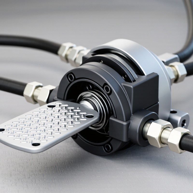
A hydraulic pedal lever valve is a manually controlled valve operated by a foot pedal or hand lever. It directs hydraulic fluid toward an actuator, often a cylinder or motor. When the operator presses the pedal, an internal spool shifts and opens a flow path. Releasing the pedal returns the spool, allowing the circuit to stop, reverse, or hold pressure. The exact action depends on the valve’s ports and center configuration.
In practical equipment, this control feels immediate. A foot movement can raise a platform, clamp a workpiece, or steer a compact machine. The operator keeps both hands available. That matters during repetitive tasks. However, response is influenced by oil viscosity, contamination, pedal travel, and system pressure. A stiff pedal may indicate linkage wear, not a defective hydraulic section. I have found that simple inspections often prevent inaccurate adjustments.
Choosing one requires more than matching thread size. Check rated pressure, flow capacity, port arrangement, return method, and mounting space. Confirm that the pedal’s neutral position matches the machine’s safe operating condition. Clean fluid and a suitable filter protect the spool from sticking. Small details matter. It is easy to assume the valve is the problem, but circuit data may suggest otherwise. One imperfect assumption can cause slow movement or unexpected drift.
Get in touch
Our mission is to develop cutting-edge clean energy technology and provide next-generation solar inverters.
Phone
(888) 598-9901
nep-usa@site_ea168614-f5f4-4298-bd5b-880b4cf8d99d
