- Spanish-Latin America
- Japanese-JP
- Chinese
- Europe
- Português-BR

Tech Support
(888) 598-9901
Hours: Mon-Fri 8AM-8PM EST
nep-usa@site_ea168614-f5f4-4298-bd5b-880b4cf8d99d
What Is a Telecentric Macro Lens and How Does It Work?
A telecentric macro lens is designed for close-up imaging when measurement accuracy matters more than ordinary visual detail. Unlike a conventional macro lens, it controls the paths of light entering the camera. Its chief rays remain nearly parallel to the optical axis, reducing perspective errors across the image.
This design helps small parts appear at a consistent scale. A screw near the lens can look almost the same size as one farther away. That consistency is valuable in machine vision, electronics inspection, dimensional measurement, and laboratory imaging. Engineers can examine a connector pin, molded edge, or printed mark without relying only on visual judgment. The lens also reduces magnification changes when an object moves slightly along the optical axis.
The optical principle is precise, but it is not magic. A telecentric macro lens still needs careful lighting, stable mounting, and accurate calibration. It may also provide a narrower field of view, a limited depth of field, and a higher purchase cost than standard macro optics. These trade-offs are easy to overlook. In practical testing, even a well-designed lens can produce unreliable results when the target is reflective or poorly illuminated. This guide explains how telecentricity works, where the lens is most useful, and why setup quality often determines the final measurement. It also considers limitations, because precision imaging deserves a realistic assessment rather than exaggerated promises.
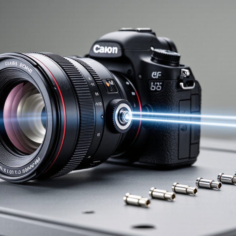
Definition and Core Purpose of a Telecentric Macro Lens
A telecentric macro lens is an inspection optic designed to keep magnification nearly constant across depth. Its chief rays travel almost parallel to the optical axis. This design reduces perspective error, so a nearby hole does not look noticeably larger than a distant one. The core purpose is reliable measurement, not simply close-up photography. Engineers use it for checking connector pins, molded edges, glass thickness, and small machined parts.
The effect is practical. A 0.1 mm height change should not create a false diameter change. The aperture stop controls the parallel light path, while the sensor records a flatter, more dimensionally stable image. However, telecentric does not mean distortion-free under every condition. Focus drift, poor lighting, vibration, and an unsuitable working distance still damage results. This is where practice gets less tidy.
The International Federation of Robotics reported 541,302 industrial robots installed worldwide in 2023, a 10% annual increase. More automated cells require repeatable optical measurements. EMVA 1288 testing guidance also separates sensitivity, noise, and spatial resolution, reminding engineers to evaluate the entire imaging chain. A lens can perform well on paper yet disappoint beside a reflective metal surface. I have seen this overlooked. Calibration targets, controlled illumination, and verified field coverage matter as much as the lens specification. A wider telecentric field may also reduce resolution or increase cost, creating a compromise that deserves measurement rather than assumption.
| Data Dimension | Technical Description | Typical or Defining Data | Practical Importance |
|---|---|---|---|
| Definition | A telecentric macro lens is an imaging lens designed so that the chief rays in the relevant optical space are parallel to the optical axis. | Chief-ray angle approaches 0° in the designed telecentric space. | It reduces perspective-related size changes and produces more consistent measurements of small objects. |
| Core Purpose | Its primary purpose is to maintain nearly constant magnification when the object moves slightly along the optical axis. | Object-size stability is prioritized over a wide field of view or compact lens size. | This is valuable for dimensional inspection, gauging, and repeatable macro imaging. |
| Object-Space Telecentricity | The entrance pupil is positioned effectively at infinity, causing chief rays on the object side to travel approximately parallel to the optical axis. | Object-space chief-ray angle is approximately 0°. | Object features at different depths appear with much less apparent size variation. |
| Image-Space Telecentricity | The exit pupil is positioned effectively at infinity, making image-side chief rays approximately parallel to the optical axis. | Image-space chief-ray angle is approximately 0°. | It can improve sensor illumination uniformity and support specific optical measurement systems. |
| Bi-Telecentric Design | A bi-telecentric lens is telecentric in both object space and image space. | Both object-side and image-side chief-ray angles approach 0°. | It provides high magnification stability and is commonly selected for precision machine-vision measurement. |
| Perspective Distortion | Perspective distortion is strongly reduced because the imaging geometry does not significantly change with small object-distance variations. | Lower apparent size change than with a conventional macro lens at comparable magnification. | Edges, diameters, gaps, and other measurable features are easier to compare reliably. |
| Magnification Stability | Magnification remains substantially more stable when the object is displaced along the optical axis within the specified working range. | Residual variation depends on lens design, focus position, aperture, and object displacement. | It reduces measurement error caused by small fixture-height or part-position differences. |
| Working Distance | Working distance is the physical distance from the lens reference point or front optical surface to the object, depending on the manufacturer’s specification method. | Usually fixed or tightly specified for a given telecentric lens model. | A stable working distance simplifies lighting, fixturing, and repeatable inspection setups. |
| Magnification Range | Telecentric macro lenses are generally optimized for a defined magnification rather than a large zoom range. | Common machine-vision magnifications include approximately 0.1× to 1×; specialized systems may extend beyond this range. | The selected magnification determines the object field of view and measurement resolution. |
| Field of View | The field of view is determined by sensor dimensions and optical magnification. | Field of view ≈ sensor dimension ÷ magnification. | A higher magnification gives a smaller field of view, while a lower magnification covers a larger area. |
| Depth of Field | Depth of field is the object-space range that appears acceptably sharp. Telecentricity itself does not automatically create unlimited depth of field. | Depth of field depends mainly on magnification, f-number, wavelength, sensor resolution, and acceptable blur. | Stopping down can increase depth of field, but it also reduces light and may increase diffraction blur. |
| Aperture Control | The aperture controls light transmission, depth of field, and diffraction behavior. | Higher f-numbers generally increase depth of field but reduce available light. | Choosing the aperture requires balancing sharpness, exposure time, diffraction, and inspection speed. |
| Parallax | Parallax is the apparent displacement of features caused by changes in viewing angle. Telecentric object-space geometry minimizes this effect. | Very small parallax within the specified object-space range. | Parts with height differences can be measured with less lateral position error. |
| Lighting Compatibility | Telecentric imaging is often paired with coaxial, dome, diffuse, or backlighting arrangements according to the object’s surface and measurement goal. | Backlighting is especially effective for silhouettes, holes, widths, and outer profiles. | Good lighting preserves edge contrast and can be as important as lens resolution for measurement accuracy. |
| Image Uniformity | Telecentric optical layouts can provide more uniform geometric projection and, in suitable designs, improved illumination consistency across the sensor. | Uniformity varies with lens design, aperture, sensor format, and illumination setup. | More consistent image geometry supports thresholding, edge detection, and dimensional analysis. |
| Resolution | Resolution is determined by the lens, sensor pixel size, numerical aperture, illumination wavelength, focus, and image-processing conditions. | Telecentricity improves geometric consistency but does not by itself guarantee higher optical resolution. | The lens and sensor must be matched to the smallest feature that must be detected or measured. |
| Trade-Offs | Telecentric lenses typically require more optical elements and a larger optical path than conventional macro lenses. | Common trade-offs include greater size, weight, cost, and a narrower operating range. | They are most justified when measurement repeatability is more important than portability or flexibility. |
| Best-Suited Applications | Typical uses include dimensional inspection, semiconductor and electronics inspection, pharmaceutical packaging checks, part-profile analysis, and precision assembly verification. | Most useful when object size, edge location, or feature position must be measured consistently. | The controlled projection reduces errors caused by perspective and minor object-position changes. |
| Selection Criteria | Selection should consider sensor size, required field of view, magnification, working distance, object depth, resolution, lighting, and acceptable measurement tolerance. | The lens specification must cover the complete object field and the required telecentric object-space range. | A correct system match is necessary to obtain the expected accuracy and avoid vignetting or insufficient coverage. |
Get in touch
Our mission is to develop cutting-edge clean energy technology and provide next-generation solar inverters.
Phone
(888) 598-9901
nep-usa@site_ea168614-f5f4-4298-bd5b-880b4cf8d99d
