- Spanish-Latin America
- Japanese-JP
- Chinese
- Europe
- Português-BR

Tech Support
(888) 598-9901
Hours: Mon-Fri 8AM-8PM EST
nep-usa@site_ea168614-f5f4-4298-bd5b-880b4cf8d99d
What Is a 5-Inch TFT LCD Module?
A 5-inch TFT LCD module is a compact visual interface found in industrial panels, medical instruments, vehicle systems, smart appliances, and portable equipment. Its practical appeal is clear: the screen fits comfortably in one hand, yet offers enough space for menus, charts, warnings, and touch controls. Typical modules use a 16:9 or 5:3 layout, LED backlighting, and resolutions such as 800 × 480 pixels. Some versions deliver 450 nits or more, helping operators read information under bright indoor lighting.
Industry data supports continued demand for small and medium displays. Omdia’s Display long-term demand forecast, 2024, tracks stable panel consumption across automotive, industrial, and embedded applications. The DSCC Quarterly Display Capex and Equipment Market Update also shows manufacturers continuing to invest in flexible and high-efficiency display production. These reports do not make every 5-inch TFT LCD module a guaranteed success. Application requirements still decide the outcome.
Display analyst David Hsieh has described the sector with a useful reminder: “The display is the most important interface between people and technology.” That idea is easy to test. A slow response, weak viewing angle, or dim backlight can frustrate users within seconds. Engineers therefore compare interface type, brightness, contrast, operating temperature, connector design, and long-term availability. A cheaper panel may appear attractive. It may also create higher integration costs later. This article examines how a 5-inch TFT LCD module works, where it performs best, and which technical details deserve closer scrutiny.
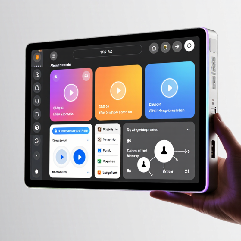
Definition and Core Purpose of a 5-Inch TFT LCD Module
What Is a 5-Inch TFT LCD Module?
Definition and Core Purpose of a 5-Inch TFT LCD Module
A 5-inch TFT LCD module is a compact flat-panel display measured diagonally across its visible area. TFT means thin-film transistor. Each pixel uses a dedicated transistor for faster switching, sharper images, and more accurate control than older passive-matrix displays.
Its core purpose is to present readable visual information in a limited space. A typical module may show menus, sensor values, maps, equipment status, or camera images. The screen usually includes an LCD panel, LED backlight, driver circuitry, and a flexible connection interface. Touch functionality is optional, not automatic. A project needs a separate touch layer or touch-enabled module.
Size alone does not define performance. Resolution, brightness, contrast, viewing angle, and color depth affect real usability. For example, a 5-inch screen with strong brightness may remain readable near a window, while a dim panel can fail outdoors. Interface selection also matters. RGB, SPI, and other interfaces require different controller resources and software timing.
During integration, I check connector orientation, mounting holes, operating voltage, and backlight current before writing display code. A common mistake is choosing a panel by size alone. That approach can create poor viewing angles, unstable power behavior, or unreadable text. I also question whether high resolution is necessary, because it may increase processing demands without improving the user experience.
Get in touch
Our mission is to develop cutting-edge clean energy technology and provide next-generation solar inverters.
Phone
(888) 598-9901
nep-usa@site_ea168614-f5f4-4298-bd5b-880b4cf8d99d
