- Spanish-Latin America
- Japanese-JP
- Chinese
- Europe
- Português-BR

Tech Support
(888) 598-9901
Hours: Mon-Fri 8AM-8PM EST
nep-usa@site_ea168614-f5f4-4298-bd5b-880b4cf8d99d
How to Choose the Best Analog Splitter 4 20mA?
Choosing the best Analog Splitter 4 20ma requires more than comparing catalog prices. The correct device must preserve signal accuracy while feeding multiple control, monitoring, or recording systems. A practical selection begins with the transmitter output, available loop power, receiver impedance, and required isolation level.
Béla G. Lipták, a respected process-instrumentation authority, emphasizes this principle: “The transmitter is only one part of the measurement system.” His observation remains valuable when a 4–20 mA loop passes through several devices. A splitter that appears suitable may introduce burden voltage, electrical noise, or unacceptable conversion error.
Check the details.
For example, a 24 VDC loop may struggle when two receivers each add significant resistance. A 250-ohm input consumes 5 volts at 20 mA, before cable losses and protection components are considered. Galvanic isolation also matters when separate cabinets use different ground references. Without it, a stable pressure signal can become a fluctuating trend on the control screen.
Look for published accuracy, temperature drift, response time, and isolation ratings. Confirm whether the Analog Splitter 4 20ma accepts active, passive, or loop-powered inputs. Installation conditions deserve equal attention. Dust, vibration, moisture, and cabinet temperature can expose weaknesses hidden in laboratory specifications.
Experience complicates the decision. The highest accuracy model is not always the best choice. It may consume more power or require unnecessary configuration. Conversely, a low-cost unit may work perfectly in a short cabinet run, but fail in a noisy plant environment. Recheck the datasheet, wiring diagram, and receiver burden before ordering. Small assumptions can become expensive field corrections.
Define the Role and Requirements of a 4–20 mA Analog Splitter
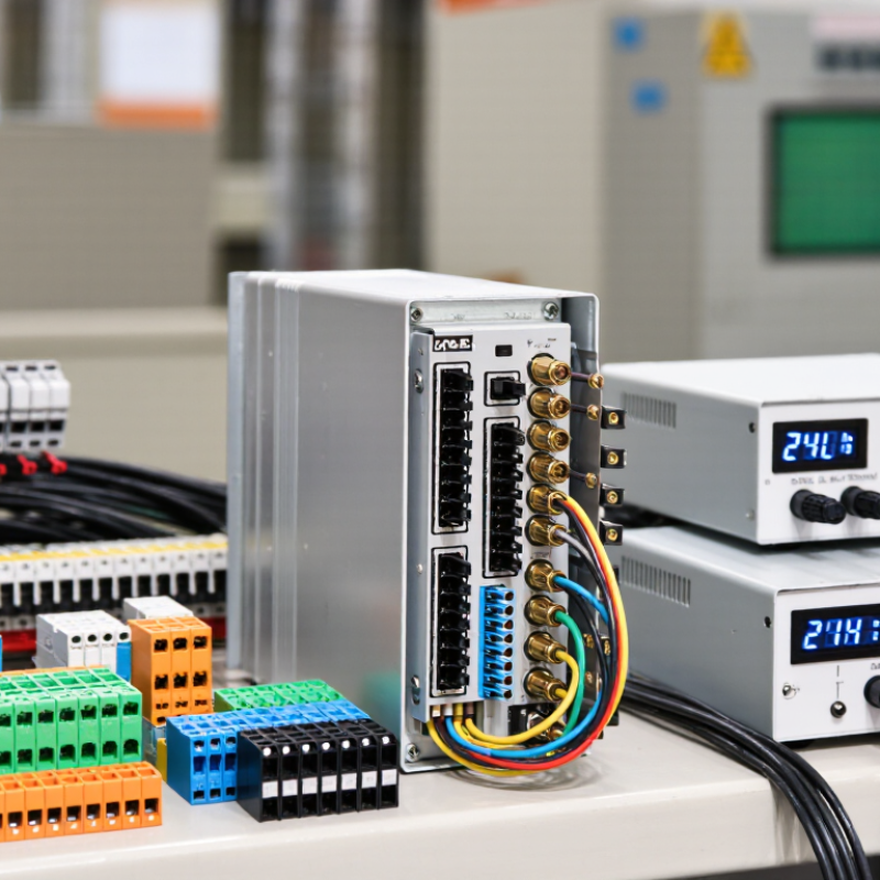
Choosing the best analog splitter starts with defining its role, not searching a catalog. A 4–20 mA splitter receives one transmitter signal and creates two or more isolated outputs. Each output may serve a PLC, display, recorder, or safety system. Confirm this path on a loop drawing. Check active or passive inputs, input resistance, isolation voltage, accuracy, response time, and power supply. A splitter can fit perfectly yet overload the loop. This mistake appears often during field retrofits.
A 2024 smart-manufacturing survey reported that 86% of manufacturers view smart operations as a major competitiveness driver. More connected loops require clearer signal management. The NE 43 process guideline identifies signals below 3.6 mA or above 21.0 mA as possible fault conditions, depending on configuration. The splitter must reproduce or clearly flag these values. Test zero, span, cable resistance, and alarm thresholds with a calibrated current source. I once treated isolation as a checkbox. The wiring looked correct, but a shared supply caused unwanted interaction. That failure changed my checklist. Also define temperature, humidity, maintenance access, and hazardous-area requirements. Leave room for drift and future channels.
Get in touch
Our mission is to develop cutting-edge clean energy technology and provide next-generation solar inverters.
Phone
(888) 598-9901
nep-usa@site_ea168614-f5f4-4298-bd5b-880b4cf8d99d
