- Spanish-Latin America
- Japanese-JP
- Chinese
- Europe
- Português-BR

Tech Support
(888) 598-9901
Hours: Mon-Fri 8AM-8PM EST
nep-usa@site_ea168614-f5f4-4298-bd5b-880b4cf8d99d
2026 How to Crimp Butt Connectors Properly?
A reliable butt splice begins with a simple question: does the crimp match the wire, connector, and tool? In “2026 How to Crimp Butt Connectors Properly,” we examine the practical details that determine whether a connection holds: stripping length, conductor placement, die selection, and a firm pull test. A few millimeters matter. Too much exposed copper can invite corrosion or contact with nearby conductors; too little can leave the barrel gripping insulation instead of wire.
For a technical reference, NASA-STD-8739.4A sets workmanship requirements for crimped electrical connections in aerospace applications. It supports a key principle: inspect the finished termination rather than trusting a tool’s click or appearance alone. That standard is not a universal household wiring guide, but its emphasis on controlled processes and inspection is useful. This article applies those habits to common insulated butt connectors and explains where product instructions should take precedence.
I could not verify a named industry expert’s published statement specifically about Crimping Butt Connectors, so I will not invent a quotation or attribute one without evidence. That gap matters. Practical advice is only trustworthy when its source can be checked. A properly sized connector, cleanly stripped wire, and compatible crimper give you a sound starting point—but even careful work deserves a second look. The barrel may look neat and still need testing.
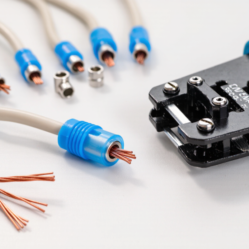
Understanding Butt Connectors and Their Crimping Requirements
2026 How to Crimp Butt Connectors Properly?
Understanding Butt Connectors and Their Crimping Requirements
A butt connector joins two wire ends inside a metal barrel, often covered by insulation. Its size must match the wire gauge and conductor type. A barrel that is too large may not compress strands securely; one that is too small can prevent full insertion. Check the connector’s specifications rather than judging by appearance alone. Small details matter.
Crimping requirements depend on the connector design. Use a crimping tool with a die intended for that connector, and follow the maker’s specified crimp location. Strip only enough insulation to expose the barrel’s full contact area. Avoid nicking or cutting strands, which can weaken the connection. Insert each wire fully, with no bare conductor extending beyond the barrel. Then make the crimp firmly and evenly.
Inspect the result under good light. The barrel should be compressed, not split, and the wires should remain seated when given a gentle tug. That check helps, but it is not a substitute for the correct tool or procedure. A neat-looking crimp can still be unreliable. I would also consider the circuit’s current, temperature, moisture exposure, and wire material before choosing a connector; skipping that check is an easy mistake. For critical wiring, use a suitable test method and the applicable equipment instructions.
Get in touch
Our mission is to develop cutting-edge clean energy technology and provide next-generation solar inverters.
Phone
(888) 598-9901
nep-usa@site_ea168614-f5f4-4298-bd5b-880b4cf8d99d
